Part 18 - First PolishingApril 11, 2019
From the menu we have implemented we can select which game mode we want to play in. However difficulty selection is not implemented yet, on both game modes. We will finish this section of the UI. After that, we work with some visual improvements.
Mode Settings - Traditional
We have defined that we will provide 3 different difficulty settings for the traditional game mode, where each directly affects how fast the speed progression will occur. To achieve this, we can create different speed curves, change the progress delta or use a combination of both.
Creating new speed curves can be time consuming, however they are very flexible in regards to the final result we are seeking. Namely, if desired we can change the initial and the final speeds, which can't be done if we just work with the progress delta. Combining both methods can, of course, give the greatest flexibility but the rate in which the "speed progress bar" will be filled will be changed. That said, in this tutorial we will only work with new speed curves (2 to be precise). Rather than adding multiple screenshots of the curves, I will just add the tables for the data points with their corresponding values, of course, with a brief description of the desired result with each curve. If you prefer to create the CSV file, the "copy/paste" contents are provided after the tables. Nevertheless, the new curves should be named cfFallSpeedEasy and cfFallSpeedHard.
The idea for the easy difficulty is to keep the shape of the curve roughly the same of the normal, however ending in a somewhat slower speed. So, for that, I have opted to begin with the same initial speed of the normal curve but ending with and "slower" value. The following table contains the data points with the corresponding values for the "easy curve". It does indeed give a much slower progress with an end speed that is still "playable":
| X (Time) | Y (Value) |
|---|---|
| 0 | 0.8 |
| 0.1 | 0.65 |
| 0.2 | 0.52 |
| 0.3 | 0.41 |
| 0.4 | 0.32 |
| 0.5 | 0.25 |
| 0.6 | 0.205 |
| 0.7 | 0.177 |
| 0.8 | 0.16 |
| 0.9 | 0.147 |
| 1 | 0.14 |
0, 0.8
0.1, 0.65
0.2, 0.52
0.3, 0.41
0.4, 0.32
0.5, 0.25
0.6, 0.205
0.7, 0.177
0.8, 0.16
0.9, 0.147
1, 0.14
As for the hard speed curve, the intention is to give a much harsh progression, still with the same initial and end speeds of the normal speed curve. With the data points from the following table we obtain a progression that, at the very beginning, seems like the same of the normal curve, but much before we reach half of the progress, the speed will be already really demanding and chances are big the game will be over even before reaching the end of the curve!
| X (Time) | Y (Value) |
|---|---|
| 0 | 0.8 |
| 0.1 | 0.58 |
| 0.2 | 0.39 |
| 0.3 | 0.26 |
| 0.4 | 0.18 |
| 0.5 | 0.135 |
| 0.6 | 0.109 |
| 0.7 | 0.09 |
| 0.8 | 0.08 |
| 0.9 | 0.075 |
| 1 | 0.0714 |
0, 0.8
0.1, 0.58
0.2, 0.39
0.3, 0.26
0.4, 0.18
0.5, 0.135
0.6, 0.109
0.7, 0.09
0.8, 0.08
0.9, 0.075
1, 0.0714
Next we update the widget, UIGM_Traditional so we can select the curves (game difficulty). The first thing we will do is rename the toggle buttons to chkEasy, chkNormal and chkHard. The prefix stands for check box, which is exactly what those toggle buttons are. Then, change the Label property on all of them to Easy, Normal and Hard, accordingly. After that is done it will be made clear that our buttons are inconsistently sized, not to mention without proper style. Open the UIC_ToggleButton widget so we can fix those issues.
First wrap the txtLabel with a Size Box and set the width and height override to 150x52. With that, it's possible to see the label is not centered, so change both horizontal and vertical alignment to Center.
As for the styling, let's first edit the Style property in the theButton widget so we can preview the changes within the designer editor window. The great thing here is that we can reuse the materials M_ButtonNormal, M_ButtonHovered and so on. This property may seem a bit overwhelming at first but it's actually simple, not to mention that we can safely ignore the Undetermined state since we are not going to use it. Nevertheless, for both the Checked Image and Unchecked Image I have used the same material, M_ButtonNormal. For the Unchecked Hovered Image and Checked Hovered Image, M_ButtonHovered. Of course, the same pattern goes for the Pressed state. But then, how to differentiate between the checked and unchecked states?! We change the Tint property of all the 3 Checked states from white to yellow (RGBA = 1.0, 0.9, 0.25, 1.0). Remember to change the Image Size property (under each state) to 64x64, Draw As = Box and Margin = 0.25. Those are the exact same brush settings we have used within the text and icon buttons.
Next change the variable property Transient to true on both stlNormal and stlSelected. You still remember the reason for that, right? Anyway, copy the style from the theButton and paste it into the stlNormal and the stlSelected. We now have an starting point for the stlSelected variable. Expand the Unchecked Hovered and change the Tint to RGB = 1.0, 0.95, 0.25, which will make the toggle button darker when it's selected. Then change the image to use the M_ButtonSelected material. Once that is done, copy that into the Unchecked Image section of the style's default value.
Now we can go back to the UIGM_Traditional. The three toggle buttons are now correctly styled but they are too close one to another. Just set the padding to 32 on all three buttons and on all 4 fields of the property. Select the horizontal box holding the toggle buttons and change its horizontal alignment to Center so the buttons are centered. The result should look like this:

And now we have to implement the functionality of those toggle buttons, namely disallow multiple selections (which is exactly the radio button behavior). Unreal Engine does not provide radio buttons, meaning that developers must implement themselves within the projects. Luckily it's relatively easy to do so. Typically we would create an internal variable and use that to control the Checked State binding of the various check boxes in the UI. I will not go into much details regarding this strategy because we can't use it. Remember, we can't bind to a blueprint property!
What we will do is create a blueprint function that will take one input, a toggle button. In its graph we first uncheck all toggle buttons and then check the one that has been given through the input. And then, when the check state changes (On Check State Changed event) we call this function. That said, let's work on the function first, CheckboxAsRadio. Add one input of the type UIC Toggle Button and name it ToCheck. To help organize the graph we use a sequence node. From the first pin we clear the check state of all 3 check boxes. From the second pin we check the ToCheck.

Every time we activate one of the toggle buttons, it will fire the On Check State Changed event. From the event handler we simple call the CheckboxAsRadio function which will uncheck all toggle buttons first. Then, we give the corresponding checkbox reference so it can be checked.

We can only select one toggle button within the UIGM_Traditional. When the widget is displayed, however, we have two problems:
- No toggle button is checked.
- There is no keyboard input focus, meaning no keyboard/gamepad navigation.
The second problem occurs throughout the rest of the menu and we will deal with that at a later moment in the tutorial. We will deal with the first problem shortly. The thing is, we will use a system that will "remember" the last difficulty selection rather than enforcing a default one. For that we will first use an internal variable that will hold the selected speed curve and use a function to "translate" so we can properly set which toggle button should be checked.
Create the new internal variable of type Curve Float (be careful to not select Interp Curve Float) and name it SpeedCurve. If desired set the default value to something, like cfFallSpeedNormal, however it will not make much difference since we will later overwrite it. Nevertheless, next we need means to associate the speed curve to the corresponding toggle button. Although its setup is a bit "messy" (in my opinion), we will use a map data structure because the alternative is the creation of a function that will need to nest Branch nodes in order to obtain the desired button. While it's not too problematic in our case of only 3 difficulty level ↔ toggle button. In other words, we will use the map system because it scales better than the branch nesting.
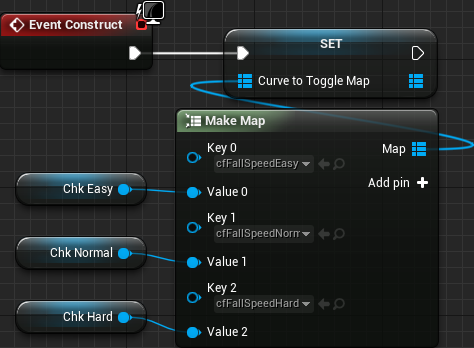
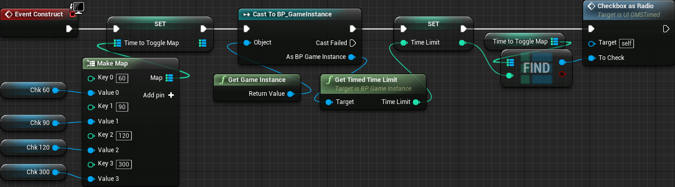
That said, create a new variable named CurveToToggleMap and initially set its type to Curve Float. Right beside the variable type dropdown menu there is an icon that, if clicked, will display another dropdown which allows selection of Single Variable, Array, Set or Map (Dictionary). When the map is selected there will be added another dropdown allowing type selection. Setting it to UIC_ToggleButton will essentially tell that the CurveToToggleMap will have a mapping that goes curve float → toggle button. In other words, each key entry in the map container will be a curve that will hold a toggle button associated with it. Unfortunately we can't assign a toggle button variable when setting the default value of the map variable, so we will have to use the Event Construct in order to initialize this CurveToToggleMap. The setup is as simple as taking the output pin of a Make node directly into the Set node. It becomes easier if you first drop the Set CurveToToggleMap node and drag from its input pin and search for the Make Map node. Click the Add Pin twice so the node is creates a map with 3 entries. Then set the keys and values according to the following table:
| Key | Value | |
|---|---|---|
| 0 | cfFallSpeedEasy | chkEasy |
| 1 | cfFallSpeedNormal | chkNormal |
| 2 | cfFallSpeedHard | chkHard |
The graph looks like this:
Shortly we will use both the SpeedCurve and the CurveToToggleMap variables.
The Initial Saving System
We have added into the UIGM_Traditional widget some variables that will be used with our system to "remember" the last difficulty level selection. We somewhat need to actually have this system implemented in order to finish working on the widget, so let's proceed with it then we come back to the finish the UI blueprint. Nevertheless, we could surely add a curve property into the game instance but that means we will end up with unused data on some game modes. This is not exactly a problem specially if you consider that this solution is pretty easy to implement. In any way, we can use the save system provided by Unreal Engine and then, from the OnBeginPlay of the game mode we can obtain this data from the save file.
The engine's save system relies on the creation of a class derived from SaveGame (USaveGame if in C++):
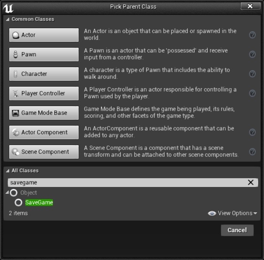
In other words, create a new save game asset and name it BP_SaveData. Each variable we add to this asset will be saved in an specified file. This means, we add a new Curve Float Object Reference variable named TraditionalSpeedCurve, compile the asset, set the default value to cfFallSpeedNormal then compile the asset again. The result of this is that if there is no save file, the game will pick, by default, the normal speed curve. We still have to access some object of the BP_SaveData. Instead of holding this object multiple times all across the project, we create a single one in the game instance blueprint class and then provide some functions to perform the necessary operation on top of the save object.
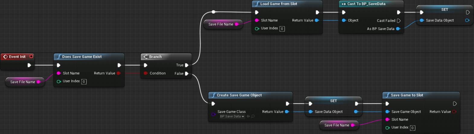
Open the BP_GameInstance asset and, if needed, click the Open Full Blueprint Editor so we can add blueprint into it. First add one string variable, named SaveFileName and then one BP_SaveData variable, named SaveDataObject. Once the blueprint is compiled it's possible to set the default value of the SaveFileName variable which I set to GameData. You can enter whatever name you want, really. Now we create a new node in the event graph, Event Init. From it we check if the save file exists with Does Save Game Exist. If positive, we load data from it using Load Game from Slot and then assign the return value (after casting) to the SaveDataObject variable. If the file does not exist, we create it with the Create Save Game Object assigning its return value to the SaveDataObject and then calling Save Game to Slot to create the file:
Next we create a Custom Event named SaveTraditionalSpeedCurve, with one Curve Float input parameter named TheCurve, which will be used to save the setting into the file. In this graph, we access the SaveDataObject to set the TraditionalSpeedCurve variable and right after that request to save the data into the file:

Lastly for the game instance (for now), is a function to retrieve the speed curve, named GetTraditionalSpeedCurve. In this case we have to create a function since events can't return values. Nevertheless, we also set this new function to Pure so when we require this data there will be no execution pin. Add one output of the type Curve Float. In there we just access Save Data Object -> Traditional Speed Curve and return it:

Remember Difficulty Selection - Traditional Mode
There are two things that we need here:
- Once the difficulty is selected, we have to save it on the game instance's save object.
- When the widget (
UIGM_Traditional) is constructed we have to load the difficulty from the save object.
To perform the first task, after one of the difficulty toggle buttons is pressed (in the UIGM_Traditional widget) we have to obtain the game instance, cast into the proper blueprint type (BP_GameInstance) and then call the SaveTraditionalSpeedCurve node, which requires an speed curve asset as input. For this, we provide the SpeedCurve variable, that should be updated as part of the OnCheckStateChanged event handling. Luckily we can condense a few nodes through the execution into a single place:

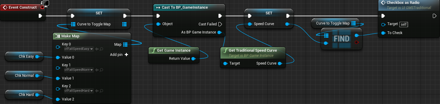
Then we can perform the second task. The logic here is somewhat simple. After setting up the map container we first load the speed curve from the save object assigning directly into the SpeedCurve variable. Once that is done we call the Checkbox as Radio using the map to obtain the desired toggle button, through its Find function:
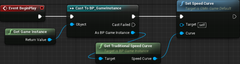
Selecting a difficulty setting, closing the game and then opening it again should keep the selection in place! Fantastic, now we can move on and make the game mode use the desired curve. Because we need access to some functions and data we have added only in our blueprint version of the game instance we are somewhat forced to use the BP_GMTraditional class to perform this task from the Event BeginPlay node. The problem is that we didn't add blueprint support to edit the internal speed curve in the C++ class. Let's fix that by adding a blueprint callable public function into our AGMInGameTraditional class:
UFUNCTION(BlueprintCallable)
void SetSpeedCurve(class UCurveFloat* Curve) { mSpeedCurve = Curve; }
Once the project is compiled, we can then obtain the game instance and call in the GetTraditionalSpeedCurve, providing the return value into the input of the function we have just created (remember, this is the BP_GMTraditional):
Because the game mode in game has been recompiled chances are high that the blueprint class has changed all of the variables to their default values. This means the Progress Delta property has been reset and we have to re-enter 0.0125. Since we are now obtaining an speed curve at the beginning of the game, there is no need to set anything in that property, but there is no harm in doing so.
And that's it! We can now select the difficulty level of the traditional game mode, load the correct map, play with the different speed variations and the game will even remember the last difficulty setting!
Mode Settings - Timed
For the timed game mode we have added the possibility to select between 4 different time limits. The default value we have been using gives 1 minute and 30 seconds (90 seconds). The actual values are completely arbitrary, really. I have decided to provide the following options, besides the 90 seconds:
- 1 minute (60 seconds)
- 2 minutes (120 seconds)
- 5 minutes (300 seconds)
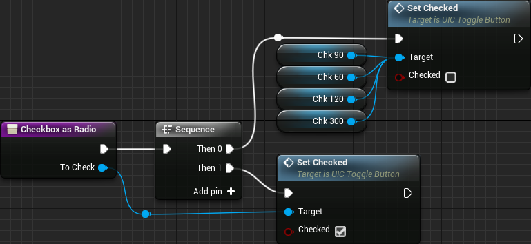
Based on this let's set the labels of the toggle buttons in the UIGM_Timed widget to 1:00, 1:30, 2:00 and 5:00. I have also renamed the toggle buttons to chk60, chk90, chk120 and chk300 respectively. Now there is an small problem. The size and spacing we have chosen (if keeping the same values from the traditional widget) won't fit on a single row depending on how the game window mode (yes, this is part of something we still have to change, which will be done soon). Because of that I have decided to add another horizontal box and move chk120 and chk300 into it. We then follow the same logic to implement the radio button behavior. That said let's first create the CheckboxAsRadio function:
Before working on the rest of the widget, let's quickly jump into BP_SaveData and update it so we can save the time limits. In this case, create a variable of integer type named TimedTimeLimit. Notice on both cases in the save game data I have prefix the variable with the name of the game mode it corresponds to. Set the default value to 90.
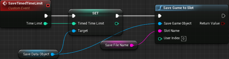
In the BP_GameInstance we create the custom event, SaveTimedTimeLimit with one integer as input. This "function" will be used to update the time limit in the save data and, save it into the file:
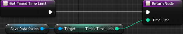
And, in the same blueprint, we create the GetTimedTimeLimit function, set to pure and with an integer as output:
Back to the UIGM_Timed widget. First create an internal integer variable named TimeLimit and then we handle the OnCheckStateChanged of all 4 toggle buttons. We have already seem the logic so I won't explain, just show the screenshot of the graph:

Then we create the map container that will perform integer → toggle button. That means, create a new variable named TimeToToggleMap changing it to Integer → Map → UIC Toggle Button. From the construction script we initialize the map then load the saved value from the file and use the map to obtain the corresponding toggle button object that should be used as the input of the Checkbox as Radio node:
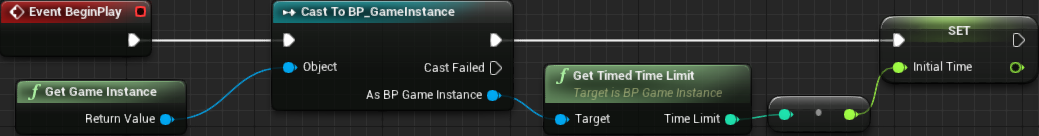
The last thing now is making the game mode use the chosen setting. This means editing the BP_GMTimed game mode blueprint asset. All we have to do here is, from the EventBeginPlay, obtain the game instance so we can call the GetTimedTimeLimit and directly set our internal variable named InitialTime. All of the logic is built on top of it, so there is no need to change anything else (notice the conversion node that is automatically added, from integer to float - remember, InitialTime is a floating point value):
And now, choosing the time limit should directly reflect in the timed game mode. And the choice should also be saved!
Animated Player Score
Right now, when score is added, the widget immediately shows the new value. Instead of doing that we can create a system where the widget displays a different value, as if it were counting to reach the new score. As it turns out, we can easily do that. In our player controller we will need a "displayed score" variable, which will contain the value we will display in the widget and will be incremented over time. The widget itself, in turn, must be changed from GetCurrentScore() to something like GetDisplayScore(). We will need another variable to tell the rate in which the display score will be updated. And finally, we have to update the display score.
We begin by adding the private floating point variable that will hold the display score into the game controller class as well as the delta that will be used to update the displayed value while "counting":
UPROPERTY()
float mDisplayScore;

UPROPERTY(EditAnywhere, Category = "User Interface", meta = (DisplayName = "Display Score Update Rate"))
float mDisplayUpdateRate;
Then, we add a public function to retrieve the display score. Notice that we do want an integer value to be used with our widget, so we are returning one with the function. We also declare the Tick() override, as we will need it to update the display score variable:
virtual void Tick(float DeltaSeconds) override;

UFUNCTION(BlueprintPure)
int32 GetDisplayScore() const { return mDisplayScore; }
In the constructor of the class we initialize the newly created variables:
AColPlayerController::AColPlayerController(const FObjectInitializer& ObjectInitializer)
{
   mCurrentScore = 0;
   mDisplayScore = 0.0f;
   mDisplayUpdateRate = 0.1f;
}
We then implement the Tick() override. In there we have to call the parent class' Tick() function as well as update the display score variable. This update is performed by simply incrementing mDisplayUpdateRate into mDisplayScore and "capping" the result to mCurrentScore:
void AColPlayerController::Tick(float DeltaSeconds)
{
   Super::Tick(DeltaSeconds);

   mDisplayScore += mDisplayUpdateRate;
   if (mDisplayScore > (float)mCurrentScore)
   {
      mDisplayScore = mCurrentScore;
   }
}
We need one last change in the player controller class. We previously added a Reset() function, meant to take the internal state to the desired initial values. Although we are capping the display score inside the Tick() function, let's also reset it:
void AColPlayerController::Reset()
{
   mCurrentScore = 0;
   mDisplayScore = 0.0f;
}
The way we obtained the score value from blueprints was through the GetCurrentScore function we have added into the blueprint function library. Let's add a new one which we can use to retrieve the display score, so we remain with the same easy blueprinting:
// Obtain the display score - this is the value to be placed in the widget (HUD)
UFUNCTION(BlueprintPure, meta = (WorldContext = "WorldContextObject"))
static int32 GetDisplayScore(const UObject* WorldContextObject);
The implementation of this function follows the same logic we have used with plenty of others in this library:
int32 UColBPLibrary::GetDisplayScore(const UObject* WorldContextObject)
{
   if (AColPlayerController* pc = GetColPlayerController(WorldContextObject))
   {
      return pc->GetDisplayScore();
   }
   return -1;
}
All that is left now is update the UI_PlayerScore widget. In there, the function we have bound to the text, we delete the GetCurrentScore node and place one GetDisplayScore in its place:

Testing now, we get the "counting up" effect, however it seem a bit slow. We can tweak the update rate of the display score by editing the Display Score Update Rate property within the BP_PCInGameDefault blueprint class. I have changed to 0.5 and it seems a lot better. Of course, this is totally personal preference!
Particle Effects
Every time we get matching runs, the involved blocks blink for a time and then are simply removed from the grid. Although a seemingly simple visual effect, adding some kind of particle effects when the blocks are removed can greatly enhance the visual experience. Unreal Engine offers a very powerful particle system and, currently, we use the Cascade editor.
Now here is a disclaimer: I cannot (and won't) pretend to know anything about particle effects creation. As I have made it clear, I'm not an artist and from all of those non programming tasks, designing particle systems is the one that I probably know less about.
Because of that, I will just tell what I did to achieve the results, much like a recipe. In any case, there is an official Youtube Playlist with a series of videos giving an introduction to Cascade. Yes, they were created using UE 4.2 and are a bit old but the information is still valid. And yes, I know Cascade will be replaced by Niagara at some point but I have to use (and showcase) what we currently have available. Nevertheless, in the description given bellow I will assume you know how to find the necessary properties/settings, which are all described in the linked tutorial series.
The idea of the effect is to generate some burst of shards, somewhat as if the block were shattered. For that I separated the system into two emitters, one for some smaller particles, which I called Sparkles and another for some bigger "shards". Hopefully my description bellow will be enough for you to replicate the effect (if you so desire). Or you could do something better! Anyway, create a new particle system asset, named PS_Shatter. In my case I have renamed the default initial emitter to Sparkles.
The material for this emitter is quite simple, but it requires a texture. Since the idea is to make very small particles, there is not need to go crazy with the resolution of the texture. In my case I went with 64x64, which is probably overkill for this usage! In any case, all I did was a radial gradient:

Once the targa is imported, change its Texture Group to Effects. Then we can create a material, named M_Sparkle, that will be used within the particle system. It should be configured so the Blend Mode = Translucent and Shading Model = Unlit. In this material we have a Particle Color node that will directly affect the output of a texture sample (holding the radial gradient texture) through a multiply. We also do the same with the alpha:

Create a new particle system asset, named PS_Shatter. Bellow I will describe module by module. Each card represents a module and when necessary (IE.: the module is not automatically added), I tell the "path" to add it, from the right click within the emitter. Remember, I'm mostly explaining thing as a recipe simply because I don't have the necessary knowledge to explain anything beyond that. I have reached this effect through trial and error as well as referencing other effects within the particle effects sample project provided by Epic Games (It should be listed in the Learn tab within the launcher).
Module: Required
Besides setting the material we have just create, M_Sparkle, we have to specify that we don't want this effect to loop over and over. In the Duration category, change the Emitter Loops property to 1.
Module: Spawn
Because I wanted a simple "burst" of particles, I first changed the rate to be 0 and then added a single element to the burst list where I set Count to 100 and Count Low to 40. If you want more particles you can either change the range in this burst list entry or change the Burst Scale, which will basically multiply the number of spawned particles.
Module: Lifetime
In there I have selected Distribution Float Uniform so each particle gets a random lifetime, inside the specified range, which I set to Min = 0.5 and Max = 0.9.
Module: Initial Size
The size of the particles is not very compatible with the grid. It becomes a lot easier to notice that if the system is temporarily (and the looping is "enabled" again just for the test) added into a scene. In any case, I have changed to Max = (5.0, 5.0, 5.0) and Min = (4.0, 4.0, 4.0).
Module: Initial Location (Location → Initial Location)
With the default setting all particles spawn from a single point. I wanted a somewhat more spread initial location. So Max = (10.0, 10.0, 10.0) and Min = (-10.0, -10.0, -10.0). Using the 3 dimensions in this game won't make that much of a difference, but well...
Module: Initial Velocity
All particles goes upwards with the default values. I wanted the "shatter effect" somewhat like an explosion, that is, shards going everywhere. So, the Distribution Vector Uniform was set to Max = (500.0, 500.0, 500.0) and Min = (-500.0, -500.0, -500.0).
Module: Color Over Life
I didn't want to change the color of the particles throughout their lifetime, so I changed to Distribution Vector Constant and the RGB to (0.85, 0.85, 0.85). If you want the particles to be more visible, keep this to full white.
And then, instead of the particles just popping out of existence, setting the Alpha Over Life to Distribution Float Constant Curve allows the creation of some sort of a fading. In there, we need 2 points with In Val = 0.0 | Out Val = 1.0 and In Val = 1.0 | Out Val = 0.0
Module: Drag (Acceleration → Drag)
With this module the particles will not keep their entire energy during the entire lifetime, rather they will slow down after the initial burst. I have set to Distribution Float Uniform then Min = 8.0 and Max = 16.0, so some particles will suffer more drag than the others.
Module: Const Acceleration (Acceleration → Const Acceleration)
I wanted the particles to also "drop" as if affected by gravity. In there, I set the Acceleration to (0.0, 0.0, -980.0).
And the result of all this is something similar to this:

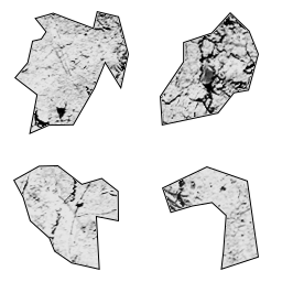
Next we add a new emitter, Shards and set it to "Solo" so the Sparkles emitter is not shown and don't distract us. The desired idea with this emitter is to generate some bigger particles, resembling shards. For that, we will use the SubImage feature, meaning that our texture will contain multiple shard shapes. We don't have to be very detailed neither high resolution, since the particles will still be small. In any case, I have chosen a resolution of 256x256 and placed four different shapes in it. In the image bellow I have painted the transparent background with white just to make it easier to see in this page:
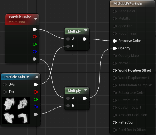
Again, after importing the targa into the project, edit the asset's Texture Group and change to Effects. Then we can work on the material, named M_SubUVParticle. As with the M_Sparkle, it should be set to Blend Mode = Translucent and Shading Model = Unlit. In there we add a Particle Color node and one Particle Sub UV, selecting the shards texture. The setup is similar to the M_Sparkle:
Back to the PS_Shatter system. Just like I have described the settings for the Sparkle emitter, I will now show the cards representing each module of the Shards emitter.
Module: Required
We select the material M_SubUVParticle and then indicate that this texture contains multiple sub images. Those settings are all under the Sub UV category.
We change the Interpolation Method to Random so a random shard is selected when spawning the particle.
Then we have to indicate that we have 2 horizontal sub images and 2 vertical sub images (the property names are pretty self explanatory).
Lastly, we have to indicate that we don't want infinite loops, just the 1, exactly like we did in the Sparkles emitter with th e Emitter Loops = 1, under the Duration
Module: Spawn
This is very similar to the Sparkles emitter. That is, change the rate to 0 and add a single entry into the Burst List. In there, we set to a lower spawn range, like Count = 15 and Count Low = 5.
Module: Lifetime
This is the exact same of the Sparkles, that is Distribution Float Uniform with Min = 0.5 and Max = 0.9.
Module: Initial Size
The default size is a bit too big. Besides that, some randomness is also nice. So, Distribution Vector Uniform (should be the default) with Max = (12.0, 12.0, 12.0) and Min = (9.0, 9.0, 9.0).
Module: Initial Velocity
We give the exact same "kick" as in the Sparkles emitter. That is Max = (500.0, 500.0, 500.0) and Min = (-500.0, -500.0, -500.0).
Module: Color Over Life
Almost the exact same settings of the Sparkles emitter, that is, Distribution Vector Constant. The color we set to RGB = (0.95, 0.95, 0.95). The alpha curve should already be set.
Module: Drag (Acceleration → Drag)
The idea is to make the drag force slightly stronger, Distribution Float Uniform with Min = (10.0) and Max = (16.0).
Module: Const Acceleration (Acceleration → Const Acceleration)
Again, just to make the shards move as if affected by gravity. (0.0, 0.0, -980.0).
Module: SubImage Index (SubUV → SubImage Index)
This is the one that will allow the emitter to know the index range within the texture. Distribution Float Uniform with Min = 0.0 and Max = 3.0.
Module: Initial Rotation (Rotation → Initial Rotation)
This will give some randomness to the rotation of the shards when they are spawned. Distribution Float Uniform with Min = -1.0 and Max = 1.0.
Module: Initial Rotation Rate (Rotation Rate → Initial Rotation Rate)
This will give some rotational motion to the shards during the particle animation. Distribution Float Uniform with Min = -2.0 and Max = 2.0.
Module: Initial Location (Location → Initial Location)
For the same reason it was added in the Sparkles emitter, so the particles don't spawn from the same point. Distribution Vector Uniform with Max = (10.0, 10.0, 10.0) and Min = (-10.0, -10.0, -10.0).
Just this emitter results in this:

And then, we disable the solo option of the Shards emitter to obtain the full result:
The next step is to spawn the particle system from the location occupied by the destroyed blocks. There are three straightforward approaches we could take in order to spawn the particle effects:
- Add a new event that will be called right before destroying a block. From the handler, we spawn the particle effect system. Doing so requires that every single game mode implement the event. Somewhat high flexibility on how many particle effects can be spawned, since the event handler will deal with the spawning. Requires an extra task when defining new game modes, which is exactly implement the event handler. In this case, the number of particle effects are defined by the game mode.
- Directly spawn the particle system from the C++ code, right before destroying the block (instead of calling an event). The amount of particle effects become restricted based on how we decide to specify which system(s) must be created. The easiest, in this case, is associate the particle with the blocks as properties of the
FBlockDatawhich is part of the theme data. - Add an event into the block class and spawn the desired particle system(s) from it. In the theme data we have to define which block class to spawn and, in this case, we would probably need to update the entries. Because the particle spawning becomes part of the final block class, we somewhat associate effect ↔ block. The flexibility is somewhat high and even if the game mode has specific needs regarding extra effects, it can be done. However, if the game mode does not need any particle effects, we have to employ extra measures so the block class don't spawn them.
Based on all this discussion I really like approach 3 and it's the one we will follow on this tutorial. That means adding event functions to the block class and we will do the same logic we have applied before, a native C++ virtual function that will, by default, call a blueprint implementable function:
// Native C++ event called whenever this block is about to be destroyed
virtual void OnBeingDestroyed() { BP_OnBeingDestroyed(); }

// Blueprint event called whenever this block is about to be destroyed
UFUNCTION(BlueprintImplementableEvent, meta = (DisplayName = "OnBeingDestroyed"))
void BP_OnBeingDestroyed();
Then we have to call this event right before destroying the block actor, which is done from the StateRemovingBlock() state function in the AGameModeInGame class:
AGameModeInGame::StateFunctionProxy AGameModeInGame::StateRemovingBlock(float Seconds)
{
   ...
   if (alpha >= 1.0f)
   {
      for (int32 cell_index : mMatchedBlock)
      {
         mGridData[cell_index].BlockActor->OnBeingDestroyed();
         mGridData[cell_index].BlockActor->Destroy();
         mGridData[cell_index].BlockActor = nullptr;
      }
      ...
   }
   ...
}
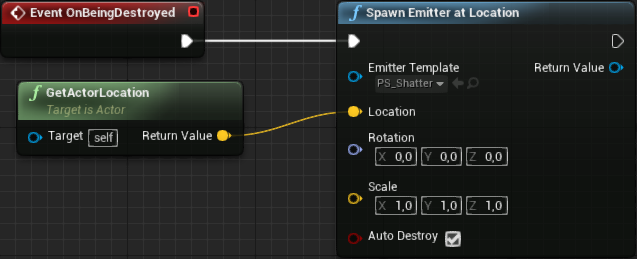
Next we create a blueprint block class so we spawn the particle effect from it. We could easily do that from C++ but really, for very simple tasks like this let's stick with the graph, specially because it will be easier to reference the particle asset, not to mention that if we rename the assets nothing else will be needed to be done. That said, create a new blueprint class, derived from the Block class, named BP_Block. In this blueprint, event graph tab, add the event handler for the OnBeingDestroyed. In it we obtain the location of the actor, and directly plug into the Spawn Emitter at Location node. In this node we also specify the PS_Shatter as the Emitter Template:
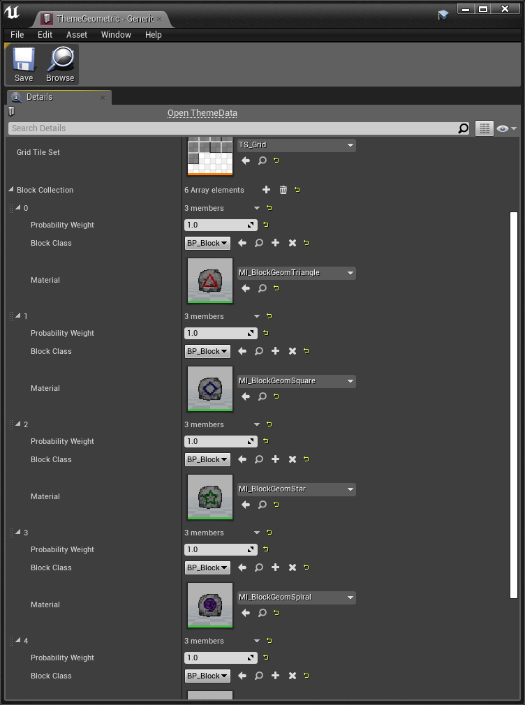
Of course, for that to work we have to edit the theme data and select the new block class to be BP_Block rather than Block. This change must be performed for each entry in the block collection:
Postprocessing
I have mentioned numerous times throughout the tutorial the fact that many of our textures are too bright when displayed on screen, even making some details of the UI not being correctly displayed. The main reason for this is the auto exposure feature of the engine. It's a post process operation that tries to correct the brightness level of the scene. We can open the project settings window and, under the Rendering category, disable the Auto Exposure property flag. This will affect the entire project however we don't have much control over the result. The thing is, if you disable, everything will seem a bit too dark (at least, a lot darker than what we seem within GIMP when editing the textures).
Another alternative is to add a Post Process Volume object into each of our scenes and setup things form it. The major advantage here is the fact that we can easily revert to the default settings if we mess up with anything, not to mention the fact that it offers a lot of extra options to tweak, albeit we will only change the auto exposure. The "cost" of this is that we will have to add the same object into each scene and setup it in the very same way each time.
Because of the "too dark" result of changing from the project settings, we will have to deal with the "copy post process settings across game maps". Let's begin with the MainMenu map. Add a Post Process Volume into it, doesn't matter its location or size because we will change an option that will make it affect the entire scene. To be more specific, the Infinite Extend (Unbound) property, which is under the Post Process Volume Settings category. Just enable it and any tweaks done within the object will be valid in the entire map.
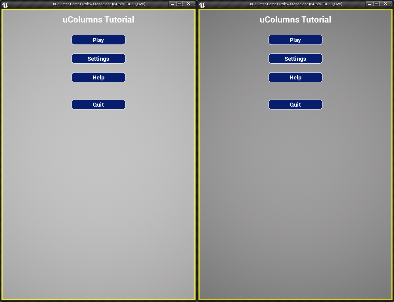
Now, under the Lens category we can find Exposure settings. In order to disable the eye adaptation feature, we have to enter the exact same value under both Min Brightness and Max Brightness (if you hover the mouse over any of those properties, the tooltip will give this exact information). After a bit of experimentation I hva found that 0.75 gives a result that I like. If you consider it too dark, decrease the value a little and if you find it too bright, increase it (again, on both properties). The image bellow, on the left is the main menu with the auto exposure enabled (default brightness settings), while on the right it's completely disabled, using 0.75 brightness:
Next, replicate this setup within the other two maps, InGameTraditional and InGameTimed. In game, it should look like this:

In this part we have finished implementing the system that makes possible for the player to choose some difficulty settings that are relevant to the chosen game mode. Also, we have slightly changed the way the score is displayed, so it "counts" up to the new score rather than just switching into it. Then we have added some (simple) particle effects that are spawned whenever blocks are destroyed/removed from the grid. And finally, we disabled the auto exposure setting that was making the rendering too bright and effectively making some texture details disappear. Yet, our game is still missing one very important thing: audio! We will deal with it in the next part.