Part 4 - The GridApril 11, 2019
Now that we have a camera, correctly set, we can start working on the PlayField, which will hold (and draw) our grid. The grid not only provides a really good visual reference for the block placement, it also helps our code with the correct coordinates in order to position the everything within the game window.
The PlayField
This is where we get a visual representation of the grid. It should provide necessary information to correctly position and size the blocks during the game play.
We want this class to allow the drawing of the grid in a way that it stays "inside" the background image but not fully using this area. The reason for that is because we want some free areas to add some UMG widgets meant to display player score and maybe some other information like the "next player piece" and so on.
We will take advantage of Tile Sets and Tile Maps. Tile Maps allows us to "tell" the number of rows and columns in order to create 2D world representations. That gives us a really nice starting point to build our grid. Another great thing about tile maps is the fact that we can obtain each cell's screen coordinates as this information can later be used to correctly position the blocks inside the PlayField/Grid.
As we tweak the number of columns and rows, the display size requirements of the tile map will change. We don't want the map to be too small or too big on screen. We have to define some "constraints" and keep the map drawn within that. Think about a "box" that should be smaller than the background image.
In order to keep the map within our defined constraints, we will make use of the image resizing algorithm (which has been described in the previous part). What this mean is that we will need some information in our class in order to scale the map size.
Another important thing related to the grid. If we leave it centered on screen, the amount of free space to fill in with the UMG widgets (player score and so on) will be distributed all "around" the grid and will be very hard reach a clean design. Rather, we will offset the grid to the left and downwards so we can concentrate the "free space" dedicated to UMG.
Now, how about the size constraints, how big should it be? In here we will have to tweak, probably a lot! However, we still have to begin with something. I have arbitrarily chosen something like occupying 2/3 of the background image. Working with 720x1080 and rounding we would end up with 480x720. And then, if those values are not good we surely can change them.
Tile Set
Let's begin this by making the tile set. Tile Sets are subdivided textures where each subdivision represents a different visual "object" or animation frame. In our case, we will need 9 subdivisions to represent top-left, top, top-right, left, center, right, bottom-left, bottom and bottom-right sections of our grid. When rendering, the engine takes only the relevant portion and applies it to the tile map's cell.
There is one important thing to keep in mind. When creating textures, one of the restrictions is to keep its dimensions constrained to values that are multiple of power of 2. They don't have to be perfectly square but it's a common practice. While on desktops going away from this restrictions often works (albeit with some theoretic performance impacts - I have never profiled this), those textures will not work correctly under mobile devices, at least when dealing with tile sets in Unreal Engine. Remember that some engines may add padding to the image data so they will work no matter the original image size.
With that in mind, we have two options here:
- Choose a texture size, divide by 3 and place our tiles distributed in 3 columns and 3 rows.
- Choose a tile size, calculate the minimum texture size and distribute the tiles leaving some unused "blank" tiles inside the set.
Option 1 means that we have "little" control over each tile's size. While it works, each tile will have sizes with uncommon values (they will not even be integers!). As an example, if we set the texture to be 256x256 then each tile would become 85.3333x85.3333. That's not exactly easy to work with inside any image processing application. Another impact comes from the fact that we will be scaling the tile map. This means that we will probably need a different scaler value to be applied to the blocks. This may not be a big deal but it does add an extra value to be checked on. In short, this option saves texture space in exchange of some extra "upkeep" and not so "nice" size values to work with.
Option 2 in a way gives more control over what is going on. As an example, if we choose that our tiles will be 64x64, then we can fit all of our 9 tiles inside a texture of 256x256. Yes, we do get 7 tiles of wasted texture space. Later on, if we go this route, we can choose the same size for the blocks and then have a single scaler value to be applied to the tile map and the blocks.
Someone may argue about a third option, where you choose the size of the texture and divide by 4 instead of 3. Well, this results in the exact same thing as option 2 in terms of tile distribution inside the texture.
You can choose any option you want as long as you know the impacts of each choice. For this tutorial though, I will work with option 2. And to be more specific, the tiles will be 64x64 (and so will be the blocks). Shortly in this part we will calculate the scaler value but right now we create our tile set inside GIMP.
Begin by creating a new image of 256x256 size. While some image editing softwares gives some very nice tools for correct positioning and easily draw each tile, GIMP is a little tricky in this aspect. The easiest way I have found follows:
- From the horizontal and vertical rulers, drag guide lines to positions 64, 128 and 192.
- Create 9 layers, each having 64x64 as size
- Paint each layer with the desired art and then drag (using the move tool) to the correct position.
I present here the tile set I have created:

I have to point some characteristics of this tile set. First and foremost, the "empty" space is actually fully transparent and the middle of each cell has 50% alpha.
This will result in a map with black borders indicating the PlayField "walls". White lines will separate each cell inside the grid. And the cell "itself" will allow the tile map to have some transparency and show the background image through the grid.
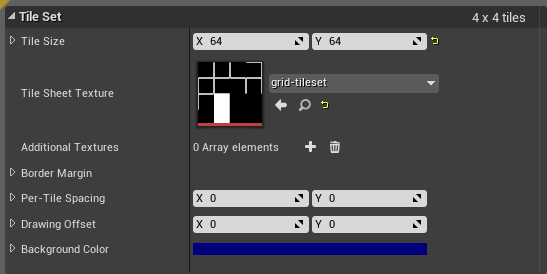
Import your tile set image file into Unreal Engine's project. Now create a new tile set asset (under Paper2D category) named TS_Grid, under the Sprites subdirectory. Edit it and make sure to set the tile size to 64 x 64 as well to select the actual texture, like this:
There is no need to change anything else. We will make use of this shortly, when we add the initial PlayField code.
The Class
We now have a tile set that will be used by the tile map, which we still have to create as part of the PlayField class. We want means to tell how many rows and columns must be generated. We do this by adding two properties, mRowCount and mColumnCount, respectively. The size (dimensions) of the tile sprite must be held, which is done with a property named mTileSpriteSize. Size (dimensions) of the background image is necessary in order to correctly calculate the final scale value for the grid map. We store this value in a property named mBackgroundSize. In order to define the "box" that will contain the grid, we use a 2D vector property named mSizeConstraint.
In order to use Paper Tile Set and Paper Tile Map, we need two object pointers, mGridTileSet and mTileMap, respectively. Finally, we need a property to hold the actual map scaling value, mMapScale.
Create a new C++ class named APlayField, derived from AActor.
#include "CoreMinimal.h"
#include "GameFramework/Actor.h"
#include "PlayField.generated.h"

UCLASS()
class UCOLUMNSTUTORIAL_API APlayField : public AActor
{
	GENERATED_BODY()
public:
   APlayField();

   virtual void OnConstruction(const FTransform& Transform) override;

   virtual void Tick(float DeltaTime) override;

protected:
   virtual void BeginPlay() override;

private:
   void BuildGrid();
   void SetGridSprites();

   UPROPERTY(EditAnywhere, meta = (DisplayName = "Row Count"))
   int32 mRowCount;

   UPROPERTY(EditAnywhere, meta = (DisplayName = "Column Count"))
   int32 mColumnCount;

   UPROPERTY(EditAnywhere, meta = (DisplayName = "Tile Sprite Size"))
   int32 mTileSpriteSize;

   UPROPERTY(EditAnywhere, meta = (DisplayName = "Background Size"))
   FVector2D mBackgroundSize;

   UPROPERTY(EditAnywhere, meta = (DisplayName = "Size Constraint"))
   FVector2D mSizeConstraint;

   UPROPERTY(EditAnywhere, meta = (DisplayName = "Grid Tile Set"))
   class UPaperTileSet* mGridTileSet;

   UPROPERTY()
   class UPaperTileMapComponent* mTileMap;


   UPROPERTY()
   float mMapScale;
};
As you can see here, we have to manually input the size of the background image (mBackgroundSize) as well as the size of each grid tile (mTileSpriteSize). This is a certain source of bugs! Imagine, for example, if we decide to change the size of the background image and forget to update these values? The result, of course, will be something not desired. For the moment we will leave in this way and then, we will try to improve the code at a later moment in the tutorial.
Moving one, let's start implementing the definitions of the class. In the PlayField.cpp, we begin with the includes:
#include "PlayField.h"
#include "PaperTileMap.h"
#include "PaperTileMapComponent.h"
#include "PaperSpriteComponent.h"
#include "PaperSprite.h"
#include "ConstructorHelpers.h"
In the constructor we have a few tasks. First of, set the default property values. Then, we create a root object, setting its mobility to Static. Granted, we have no interest in moving the grid around the screen. This setting will probably not impact our project that much since we are not dealing with scene lighting. The tile map should be created later and attached to the root component. Finally, obtain one of the engine's resource material. This material has translucency set for sprites and will allow our tile set to make use of the alpha. The code:
APlayField::APlayField()
{
   // Set this actor to call Tick() every frame.  You can turn this off to improve performance if you don't need it.
   PrimaryActorTick.bCanEverTick = true;

   mRowCount = 16;
   mColumnCount = 9;
   mTileSpriteSize = 64;
   mBackgroundSize = FVector2D(720, 1080);
   mSizeConstraint = FVector2D(480, 720);

   RootComponent = CreateDefaultSubobject<USceneComponent>(TEXT("DefaultRootComponent"));
   RootComponent->bHiddenInGame = true;
   RootComponent->bVisible = false;
   RootComponent->SetMobility(EComponentMobility::Static);

   mTileMap = CreateDefaultSubobject<UPaperTileMapComponent>(TEXT("PlayfieldTileMap"));
   mTileMap->AttachToComponent(RootComponent, FAttachmentTransformRules::KeepRelativeTransform);

   static ConstructorHelpers::FObjectFinder<UMaterialInterface> tmap_mat(TEXT("/Paper2D/TranslucentUnlitSpriteMaterial"));
   mTileMap->SetMaterial(0, tmap_mat.Object);
}
Next we code the OnConstruction(). Quoting its functionality from the documentation:
Called when an instance of this class is placed (in editor) or spawned.
Adding to that, every time we make any property change in the editor, this will be called. This means that anything we do in our code to properly build the grid, should go in there.
The first thing we do is check if the tile map needs initialization. Normally it isn't as the tile map component creates one by default. Nevertheless, we add the code just to make sure no errors will come bite us later. Next, we check if it's necessary to add a layer to the tile map, since at least one is necessary for the map to work. By default the component's initialization does not add this one layer. While this component provides the feature to add multiple layers, we will not do so in this project. Finally we actually build the the grid (BuildGrid()) and procedurally set each map's cell to use the correct tile from the tile set (SetGridSprites()):
void APlayField::OnConstruction(const FTransform& Transform)
{
   Super::OnConstruction(Transform);

   // Initialize the tile map if it's not valid
   if (!mTileMap->TileMap)
      mTileMap->CreateNewTileMap(mColumnCount, mRowCount, mTileSpriteSize, mTileSpriteSize, 1.0f, true);

   // Add a Layer to the tile map if there is none
   if (mTileMap->TileMap->TileLayers.Num() == 0)
      mTileMap->TileMap->AddNewLayer();

   BuildGrid();
   SetGridSprites();
}
In a moment we will implement BuildGrid() and SetGridSprites(). For now, let's just add the definitions for Tick() and BeginPlay(). At a later moment we will add functionality to both.
void APlayField::Tick(float DeltaTime)
{
   Super::Tick(DeltaTime);
}

void APlayField::BeginPlay()
{
   Super::BeginPlay();
   RootComponent->bVisible = false;
}
To the grid builder, BuildGrid(). In there we have to make sure the tile map is holding the correct grid size (rows and columns). Right after that, calculate the map scale, offset its position and finally apply those values to the tile map.
The map offset maybe require some explanation. Here we calculate the actual relative position. The first thing to take in mind is the fact that when we set the map's position, it actually places the center of the cell 0 (row 0, column 0) at the designated values. This means that we have to take "half cell" into account when calculating the final desired position. The second thing is the way we have setup everything up until now, which makes the very center of the camera view become the origin of the scene (0, 0). Finally, the cell in question (row 0, column 0) is the top left of the map grid from the camera's point of view (which is also ours).
The X position is relatively simple. Because we have centered the image within our camera, the left border of the background image is actually the negative of half of its width. As mentioned, we have to take "half cell" into account and "move right" (add to value we already have).
For the Z position we have something similar, regarding "negative half height". However, it would place the top-left cell at that position. We need to "move up" the entire resulting height of the grid. And to do that, we have to add to the previously computed value. Finally, that "half cell" thing. If we don't take that into account, the result will keep the grid slightly above what we want. So, we have to subtract from the result we already have.
Now, to the code:
void APlayField::BuildGrid()
{
   // Used to obtain current tile map sizes
   int32 mrows, mcols, mlayers;
   mTileMap->GetMapSize(mcols, mrows, mlayers);

   // Make sure the tile map is holding the correct grid size
   if (mrows != mRowCount || mcols != mColumnCount)
   {
      mTileMap->ResizeMap(mColumnCount, mRowCount);
   }

   // Calculate map/tile scale factor
   const float grid_width = mColumnCount * mTileSpriteSize;
   const float grid_height = mRowCount * mTileSpriteSize;

   const float s1 = mSizeConstraint.X / grid_width;
   const float s2 = mSizeConstraint.Y / grid_height;

   float total_grid_width = mSizeConstraint.X;
   float total_grid_height = mSizeConstraint.Y;

   if (s1 > s2)
   {
      total_grid_width = grid_width * s2;
      mMapScale = s2;
   }
   else
   {
      total_grid_height = grid_height * s1;
      mMapScale = s1;
   }

   // Calculate the map position
   const float half_cell = mTileSpriteSize / 2.0f * mMapScale;

   const float xpos = -mBackgroundSize.X / 2.0f + half_cell;
   const float zpos = (-mBackgroundSize.Y / 2.0f) + total_grid_height - half_cell;

   // Finally apply those values to the tile map
   mTileMap->TileMap->TileWidth = mTileMap->TileMap->TileHeight = mTileSpriteSize;

   mTileMap->SetRelativeScale3D(FVector(mMapScale, 1.0f, mMapScale));
   mTileMap->SetRelativeLocation(FVector(xpos, 0.0f, zpos));
}
Finally, we setup each of the tile map's cell to use the correct tile from the tile set. The algorithm iterates through each column and each row, setting up the tile index.
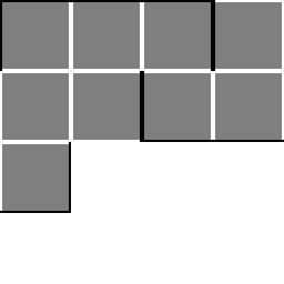
The other aspect of this snippet is the tile index inside the tile set. This will greatly change depending on how you have distributed the tiles inside the tile set image. The following image showcases the indices inside a tile set image subdivided by 4 rows and 4 columns:

The way I have distributed the tiles, as shown previously in this part, was done so the index grows continuously, in this order (tile index inside parenthesis): top-left (0), top (1), top-right (2), left (3), center (4), right (5), bottom-left (6), bottom (7) and bottom-right (8).
What all this means is this: when we are at the first column of the tile map, the first cell should have tile index 0 (top-left). Then when iterating through the row, we have to choose index 3 (left) until we reach the last cell of the column, when the index should be 6 (bottom-left). On subsequent columns, not counting the last one, the first row takes tile index 1 (top). Then, during iteration of rows the index should be 4 (center) until the last row, when index becomes 7 (bottom). On the last column this pattern goes from index 2 (top-right) to 5 (right) and finally 8 (bottom-right).
With that pattern in mind, we take a "base index", which will be either 0 (first column), 1 or 2 (last column). In the first iteration of the row loop, we directly use this "base index". Later on, the index should be either 3 (first column), 4 or 5 (last column) until the last iteration of the row loop, when the index should be 6 (first column), 7 or 8 (last column). So, all we have to do is add 3 to the "base index" when inside the second iteration of the row loop and then another 3 when inside the last iteration. The code:
void APlayField::SetGridSprites()
{
   for (int32 col = 0; col < mColumnCount; col++)
   {
      const int32 base_index = (col == 0 ? 0 : (col == mColumnCount - 1 ? 2 : 1));

      for (int32 row = 0; row < mRowCount; row++)
      {
         const int32 index = base_index + (row == 0 ? 0 : (row == mRowCount - 1 ? 6 : 3));

         FPaperTileInfo tinfo;
         tinfo.TileSet = mGridTileSet;
         tinfo.PackedTileIndex = mGridTileSet ? index : 0;

         mTileMap->SetTile(col, row, 0, tinfo);
      }
   }
}
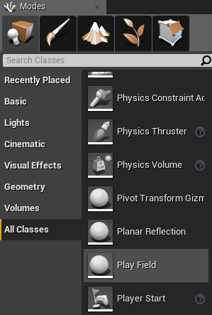
Build the project and once that is completed, inside the Engine Editor the object "pallette" should have a new entry, Play Field, to be dragged into the scene:

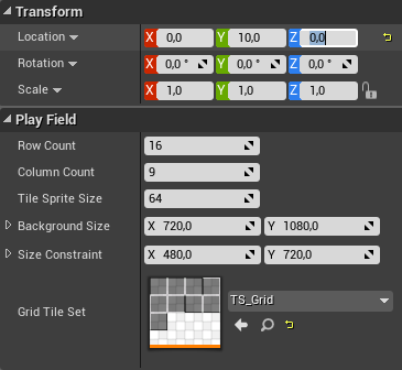
So, only in the InGameTraditional map, add this object into the scene and set its Location property to (0, 10, 0). These coordinates position the grid slightly in front of the background image. We do this just to make sure there is no "location conflict" when rendering grid and image and since our camera is set to Orthographic Projection, we still get the desired visual result. Once the Location is set, a contour of the grid should appear, showcasing its correctly "shifted position". Now, in order for the grid to actually appear, we have to "tell" the Engine to use our tile set. In order to do that, just change the Grid Tile Set property of the Play Field object to the tile set sprite you have created:
As soon as this change is done, the grid tiles should be applied to our object. And then, this is the result:
Now, the "empty" space that we have left for UMG is way too big for our needs. Luckily we can tweak that by editing the Size Constraint property of the Play Field object. So, let's increase that from 480x720 to 500x880. This should be enough for our needs. I encourage you to try and change the grid size properties and see how everything is working up until this moment!
While we still don't have much to see, we at least have our grid being fully built and rendered. And the greatest thing here is that we can already tweak some values in order to change how the grid is placed within our screen.
In the next part we will start coding the ABlock actor class, which will hold information about each block type as well as performing the correct rendering.


